Tuesday, May 22, 2018

MiniPA 70 watt HF Amplifier Unboxed and Assemble Transformer Cores

22nd of May, 2018  Hope everyone is enjoying Spring!


Watched as much W5KUB coverage of Hamvention 2018 last weekend as was allowed by the XYL and the ever present "Honey Do" list. Been busy in Real Life so bench activity has suffered.

New Project - MiniPA 70 watt HF Amplifier Kit

These kits are current available on eBay for $15-25 USD under various headings.

The Pluses:

  • Small 
  • Runs on a 13.8Vdc supply.
  • Cheap
The Minuses:

  • Comes with NO DOCUMENTATION - Need to go online even for the schematic.
  • Not Complete - Need to buy several other components to have a working Amp
NOTE: Here are a few youtube videos and websites discussing this kit that I found helpful
.
https://www.youtube.com/watch?v=CeegQYZ25J0

http://pa-11019.blogspot.com/2016/11/diy-kits-70w-ssb-linear-hf-power.html

http://www.oe1cgs.at/wp-content/uploads/2018/02/50W-HF-PA.pdf

https://www.dk9jc.de/blog/equipment/142-diy-kits-70w-ssb-linear-hf-power-amplifier-ft-817-kx2-kx3

Google "SSB HF 70W AMP" key words for latest links.

NOTE: What is NOT included
 (Needed to make a working HF Linear Amplifier for Amateur Radio.)
  • HeatSink
  • Thermal Paste (Heatsink Compound)
  • Bolts / machine screws (6) to mount PCB and TO-220's to Heatsink.
  • 12Vdc Fan
  • Enclosure
  • Panel mount SO-239 connectors
  • Power supply connector
  • Power Switch
  • Fuse and Holder
  • Low Pass Filter for desired Ham band(s)
  • RCA female panel connector for PTT
  • 50 Ohm COAX and Hookup wire
  • Power on LED (optional)

MiniPA 70 watt HF Amplifier:  Unboxed


Here is the kit parts all laid out:
As usual with Chinese kits no documentation is included, all parts were loose packed in a bubble wrap bag (no ESD protection for FETs) Two extra TO-220 insulation pads and washers were included. 

The PCB is only about 2" x 4" inches - my kit had all the SMD components already soldered to the PCB,  some of these kits do not so "buyer beware" check auction listing closely, an extra $2 may save you 2 hours of bench time.
The PCB also has Die-cut pieces that are cut out for the T1 & T2 transformer core assemblies.

MiniPA 70 watt HF Amplifier: Assemble the T1 & T2 transformer cores


Here is the Transformer cores ready to solder the tubes to the PCB pieces


Transformer cores after soldering the PCB pieces to the tubes.

Checking PCB for fit on Heatsink I brought

Wednesday, May 9, 2018

Let's Build Something - Audio Amp

May 9, 2018 

Let's Build Something - Audio Amp

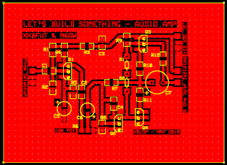
Pete Juliano N6QW co-authored a series of articles for "QRP Quarterly" over three years ago titled "Let's Build Something". The "something" was a beginners Home Brew SSB Transceiver for 40 Meters broken up into two main parts and further sub-divided by each stage.

Part I was a Direct Conversion Receiver and the first stage was a discrete component Audio Amplifier.  Pete's build method was a Manhattan style using W1REX MeSquares.
  
I converted the audio amplifier circuit to K7QO Chuck Adams' "Muppet" style PCB design. I use the free ExpressPCB software (run under WINE in Linux), to design, then print the top copper layer to a PDF.  Import the PDF into GIMP to "flip" the image.  The "flipped" image is then laser printed on glossy photo paper. Ready to do the toner transfer to bare (shiny & clean) copper clad pcb board. Which is then etched.

Sound like a lot of steps but it goes quick after you have the design.

 PCB DESIGN

"FLIPPED" IMAGE

COMPLETED PCB READY FOR SOLDER

K7QO Chuck, uses a thermal laminator to generate the heat and pressure to transfer the toner to the PCB material, He has it down to a science. I use a GE clothes iron than does the job as long as I leave a wide margin with no traces from the edge of the PCB.

The Mouser order is here with the SMD parts so I'll start melting solder in the next couple days. (Real Life has been interfering with bench time!)

73
AB1OP Ralph

Addendum:

LBS_AUDIO_AMP_partslist
part ID for AB1OP PCB diagram
================================
C1  10 NF
C2  100 NF
C3  100 NF
C4  150 PF
C5  10 UF ELECTROLYTIC (observe polarity)
C6  4.7 UF ELECTROLYTIC (observe polarity)
C7  470 UF ELECTROLYTIC (observe polarity)

R1  100K
R2  10K
R3  100 OHM
R4  1K
R5  470 OHM 1/2W
R6  10K POT
R7  100K
R8  10K
R9  10K
R10 1 OHM 1/2W
R11 1 OHM 1/2W
R12 1.3K

D1  1N4148 (observe polarity)
D2  1N4148 (observe polarity)

Q1  2N3904 NPN (observe orientation - flat right)
Q2  2N3904 NPN (observe orientation - flat right)
Q3  2N3904 NPN (observe orientation - flat right)

Q4  2N3906 PNP (observe orientation - flat left)


Tuesday, May 8, 2018

May 7th, 2018
Converting to 4-pin Microphone Connectors

 Photo above: Diagrams of the connections for each part. (solder lugs side)

On the Bench: 
Decided to standardize my microphone connection for my two Bitx transceivers.  The four 4 pin Foster connector was chosen for ease in converting cheap Baofeng Speaker-Mics or old CB microphones to the task.
Photo above:
Here is my second Bitx Xcvr being prepped for a microphone connector transplant.  The original connector I installed a year ago was an eight pin Foster, (must have been the cheapest on the search!)
Photo above:
My two Bitx Xcvr's sporting the 4 pin microphone sockets. The top one has no internal speaker. It was encased in an old PC-ATX power supply chassis and was an early microphone connector transplant recipient!  Originally I had installed two stereo jacks (2.5mm & 3.5mm) so I could use an unmodified Baofeng Speaker-Mic 2 prong plug.  A problem arose when after leaving the mic plugged in for a long time the jack contacts would weaken enough for the plug to shift out and short the PTT contact through the speaker coil to ground, (No DC blocking cap on speaker+ line in the mic, must have cost too much in production.) This caused the powered on Bitx to transmit uncontrollably. Installing the new 4-pin mic socket and plug took care of the problem and was more secure.

In Summary:
Having the same  microphone connector for both Bitx Xcvrs' is convenient and well worth the time for conversion.

Sunday, May 6, 2018

Amateur Radio Callsign AB1OP - A timeline

Winter 2010-2011 - Studied for Amateur Radio License Test(s) using FREE online study guides and practise tests

January 2011 - Brought a 1993 "ARRL Handbook for Radio Amateurs" from eBay ($9.46) 

March 27, 2011 - Took the VEC exam during the Androscoggin Amateur Radio Club
"AndyFest" 2011 passed the Tech, General and Amateur Extra.

April 4, 2011 - Official FCC ULS Grant Date of callsign AB1OP to Ralph L. Mills, Town of Greenwood, Oxford county, Maine  USA.

August 2012 - Brought a practise Telegraph Key off eBay ($5) assuming I would have to home brew a basic QRP CW transmitter and Receiver if I was going to afford to get "On the Air" Started to use Android Apps on my tablet to learn Morse code.

November 2014 - Ordered a BaoFeng BF-UV-5RE HT Radio because "A BaoFeng in the hand is better than an Icom in a warehouse". Could only successfully connect to local repeater while outside standing on the metal shed roof!

February 11, 2015 Brought a Callsign Name tag from Lake Region Awards.

March 2015 - Brought an ICOM IC-2300H VHF 2 Meter Xcvr to use as a base station because "standing outside on a metal shed roof in the middle of Winter just in hopes to talk with someone was NOT something I could make into a "Standard Operating Procedure"."

Antenna:  The Tram 1185 Magnet Mount 2 Meter placed on the metal roof was replaced by the N9TAX "Slim-Jim" roll up. 

Power: Using my salvaged PC-XT power supply 12V rails proved to be inadequate for any output power greater than 5 watts on the Icom. (Supply protection tripped requiring the PS need for a reset.)  Brought a Chinese bare 30A(?) Switching PS 12V adjusted to 13.8V. This supply was able to run the Icom on its' 5,10 and 25 Watt output levels. The 65 Watt output power setting caused the Voltage from the cheap PS to sag, so it is not used as the 10W power level works for the local repeater..

(To be Continued)

Saturday, May 5, 2018

Happy cinco de mayo 2018. 
Just wanted to setup a blog for my Amateur Radio thoughts, activities and projects. 
I have been using my Google+ and Facebook accounts to record my Ham Radio adventures on the Amateurlogic.tv group and several BITX groups. Some of this information may leak over to my QRZ pages two or three times a year.
I want to organize this blog to be my central information collection, distribution and archive.
I'll begin by reposting many of my Google+ and Facebook entries here, while filling the gaps with my half-witty commentary! 73 AB1OP_Ralph